Non Default Rules are a set of rules that we apply on critical nets which cannot meet the timing requirement due to variety of factors leading to loss of signal integrity. It tries to provide the minimum spacing and minimum width for particular nets.
Delay is an important aspect of a signal net and it is constituted by the R and C components.
R= δL/A --------------------------(1)
C= έA/d ---------------------------(2)
RC = δLέ/d -----------------------(3)
The R and C factors are completely independent from the width but the factor resistivity δ is dependent on width which will affect the RC.
C= έA/d ---------------------------(2)
RC = δLέ/d -----------------------(3)
The R and C factors are completely independent from the width but the factor resistivity δ is dependent on width which will affect the RC.
Min width
Due to the boundary scattering effect, it’s seen that the mobility of the electrons is tampered because the electrons will hit the wire boundary and will have a non linear movement which thereby results the resistivity to increase. The change in resistivity δ will directly change the RC. Now if we increase the width of a net, boundary scattering could be avoided which will result the mobility to be improved and the resistivity as such will decrease and eventually the R and C components of the net are also reduced. So this will be the minimum width requirement of the net to reduce the violations due to RC. Fig 1 shows the variation in resistance with width.
Due to the boundary scattering effect, it’s seen that the mobility of the electrons is tampered because the electrons will hit the wire boundary and will have a non linear movement which thereby results the resistivity to increase. The change in resistivity δ will directly change the RC. Now if we increase the width of a net, boundary scattering could be avoided which will result the mobility to be improved and the resistivity as such will decrease and eventually the R and C components of the net are also reduced. So this will be the minimum width requirement of the net to reduce the violations due to RC. Fig 1 shows the variation in resistance with width.

Min spacing
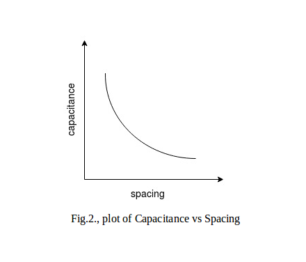
With the scaling down in technology it’s become more important than before to keep the various design elements in proper proportions to avoid any impact to the signals that flow in the compact block or chip. If these signals that are flowing in metal wires are placed too close to each other, the one carrying a higher signal strength may bring reverse effects on the one carrying a weaker one due to what’s called a coupling parasitic. As a matter of fact, the signal being affected might lose its integrity and produce unwanted results leading the whole design to fail. This is where the concept of minimum spacing comes into play. This parameter would thereby regulate the amount of coupling capacitance that form between the aggressor and the victim wires. Fig 2 shows the variation of capacitance with spacing.
NDR analysis is done in order to obtain these minimum and maximum parameters and then choose the optimum value of spacing and width that will cause the least harm to the routed design. To obtain the timing with different combination of layer/width/spacing, a cage structure is built as shown in the Fig3. There are drivers and sink cells put at opposite ends of the nets as shown. We route one net for required length considering how the channels are in the design with a certain width and spacing in a layer and thereby the driver of desired size drives it as shown. The layers above and below this layer are also filled with routing up to 50% depending on the design congestion. STA is run on this structure to find out the timing. Different scenarios of driver size, net width and spacing are thereby analyzed to come to the reasonable values. If these obtained values causes congestion then the next set of values are considered as NDR rule. Fig 3 shows the NDR analysis setup.

The different colors of stripes denote different metal layers stacked on each other.
quimaagji_2001 Hector Buoy https://www.awazul.com/profile/Mizu-No-Miyako-Bikini-Of-One-Piece/profile
ReplyDeletepostcarczines